


Creating edge moulding on parquet floors

Description

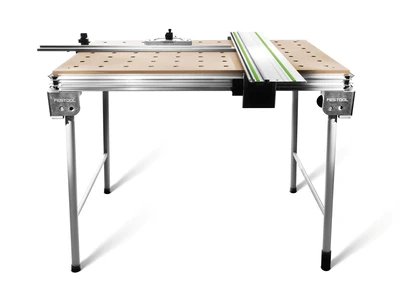
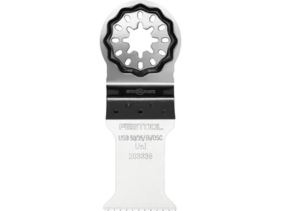
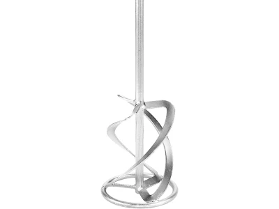
Tools/accessories


Alternative tools


Preparation/set-up
-
Aligning the moulding
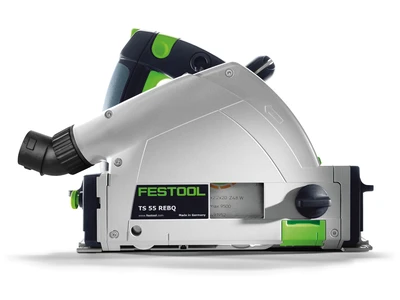
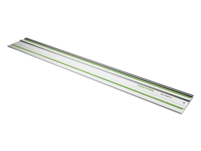
Lay the guide rail and the plunge-cut saw out ready, as the width of the parquet moulding must be neatly cut. Set the cutting depth of the plunge-cut saw to the height of the parquet.

-
Defining the width of the parquet moulding
Define the width of the moulding and align with the angle to 90° in all corners with the angle and mark.


Procedure
-
Positioning the guide rail
Position the guide rail on the marker point and cut neatly. Dispose of parquet offcuts immediately.

-
Aligning to all walls
Repeat the whole process on all sides so that, as here, for example, there is a neat right angle. Then vacuum everything.

-
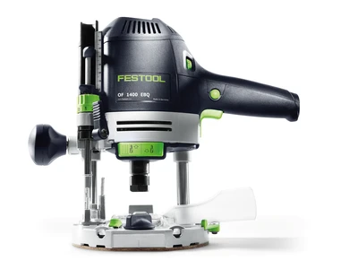
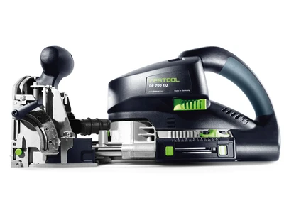
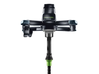
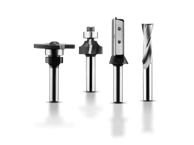
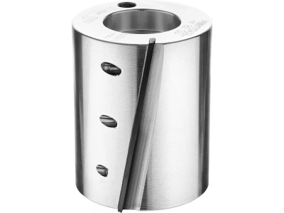
Preparing the router
Finding the correct groove cutter In this example, I can use the tongue side of my floorboards as a connector and need this router for the appropriate groove thickness. This can vary according to the thickness of the tongue. If necessary, go through the surfaces in two different thicknesses to make the groove a bit wider. Then vacuum everything again.

-
Fitting a groove cutter
Now the groove cutter can be fitted on the router very easily using the ratchet system. Please ensure that it is inserted up to the mark.

-
Setting the routing height
The routing height is determined using one of the floorboards which are to be fitted, whereby we loosen the rotary knob on the router, plunge the router up to the upper edge of the groove and scan and then tighten the rotary knob again. Determine the setting using the adjustable stop and depth setting on the router, as in the description. The routing depth is automatically generated with the bearing guide on this router and the machine guided.

-
Routing the groove on all sides
Connect the router to the power supply and extractor.
Test on a sample piece first whether the tongue and groove can be connected neatly. If everything fits together, the groove can be routed on the floorboards. Please use both hands to guide the router. Be careful at the ends. Do not tip over, or tilt the machine.
-
Routed groove

-
Moulding cut
In order to achieve the same spacing to some extent, each time adapt the lengths of the floorboards from the centre outwards.

-
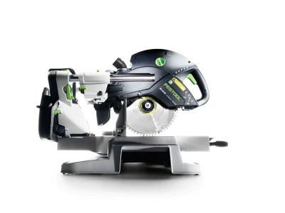
Angle transfer 1
If it had not previously been possible to create a right angle, the angle can be produced with a bevel …

-
Angle transfer 2
… and be transferred to the special Kapex angle bevel. In this way, a lot of time can be saved through the saw working perfectly in conjunction with the fence. See description.

-
Marking the inner edge
And as an aid, lightly mark the mitre direction. So there is no confusion with the different cross-cuts.

-
Positioning the bevel
Position the bevel, move the mark to the spot lighting, set and secure the precise angle.

-
Cutting
Place on the marker and cut.

-
Adjusting the width
Measure out the width of the moulding and adjust using the CS 50. Cut all parts with precision.

-
Laying everything dry
Check for precision when laying

-
Almost finished
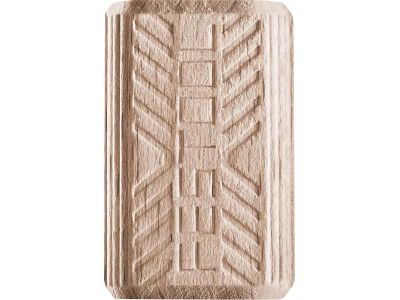
Now it only remains for the Domino dowels to be placed at the corner joint.

-
Marking the domino joint
Here there are two markings.

-
Fitting the 4 mm Domino router
Inserting the cutter

-
Domino settings
Depth 20 mm, and set the middle floorboard height. Set one side per corner with the exact width of the Domino dowel.

-
Counterpart
Rout the counterpart wider so that it can be pushed in better.

-
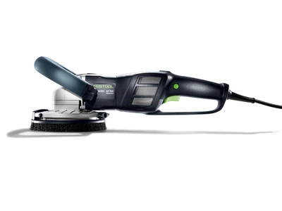
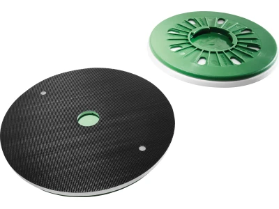
Blunting all cut edges
To achieve a small chamfer, all cut edges must be lightly sanded.

-
Test
Before gluing, test again whether everything can be pushed together with no problem.

-
Gluing the moulding
Gradually apply the adhesive, glue the floorboards carefully and join. Then clamp the whole thing from the edge with wooden wedges.

-
Bringing together the corner joints
Now step 20 stands the test with the wider routing, since the board can be better and more easily positioned and pushed in.

-
Glued surfaces with the edge moulding


-
Our illustrated guides and work results are documented working steps that we have performed in practice. They are individual examples and do not guarantee or promise that users will obtain the same results. The results will depend on the user's experience and skill, as well as the material being used. Illustrated guides do not replace any Festool operating manuals and/or safety instructions. Liability for ensuring that the information, instructions and applications are free from content defects and defects of title, in particular with regard to the absence of defects, correctness, freedom from third party intellectual property rights and copyrights, completeness and fitness for purpose, is excluded. Claims for damages made by the user, regardless of their legal basis, are excluded. These liability exclusions are not applicable if the damage was intentional or caused by gross negligence, or in cases of statutory liability.
We cannot accept liability for damage resulting from defects.↑
